


Worldwide Express Delivery • Ships from the US • Free Shipping
Secure & Protected • Purchase Orders Accepted
Payment methods
Your payment information is processed securely. We do not store credit card details nor have access to your credit card information.
Security
Genuine Products • Guaranteed Compatibility • We Ship Internationally

No Extra Payments Required • No Additional Costs
Tariffs, duties, taxes, and all applicable fees are included. Door-to-door delivery is provided under Delivered Duty Paid (DDP) terms. All shipments are fully tracked and insured.
Door-to-door delivery is provided under Delivered Duty Paid (DDP) terms, with full tracking and insurance coverage
We manage all worldwide import and customs clearance. All tariffs, duties, taxes, and customs fees are included. No additional charges upon delivery.
Tariffs, All Taxes, Duties and Fees are Included
There are no additional costs or extra payments required. All shipments are fully tracked and insured. Duties, tariffs, taxes, and customs fees are included. We ship DDP via UPS, FedEx, DHL, USPS, couriers, redirectors, or the carrier of your choice.
Pay in your Currency, Easy Transfer
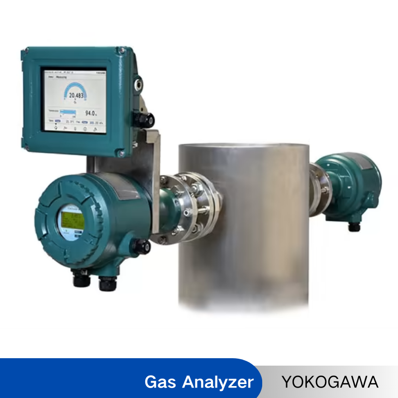
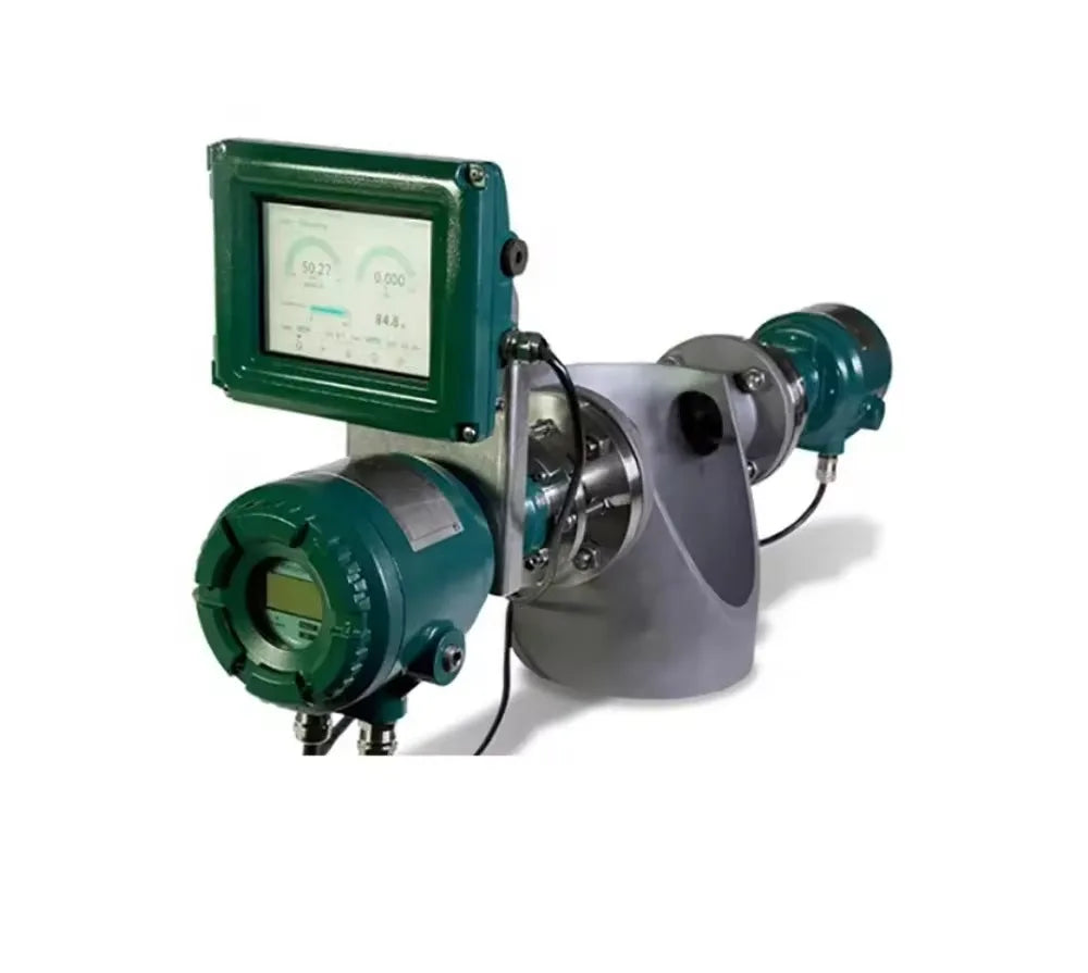
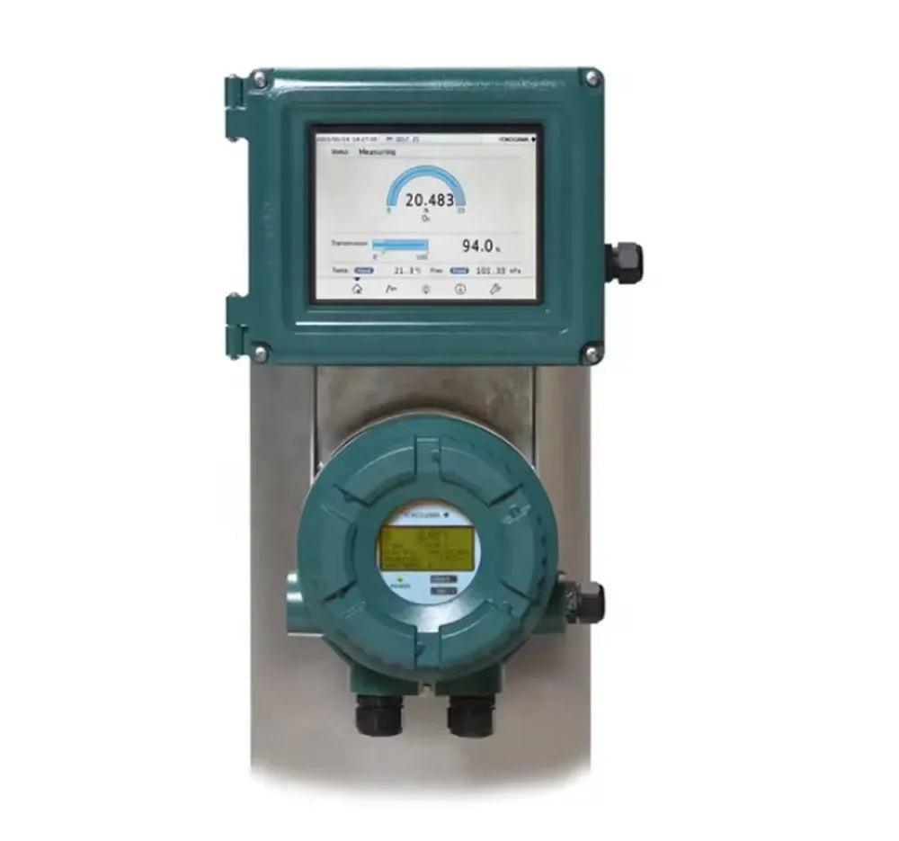
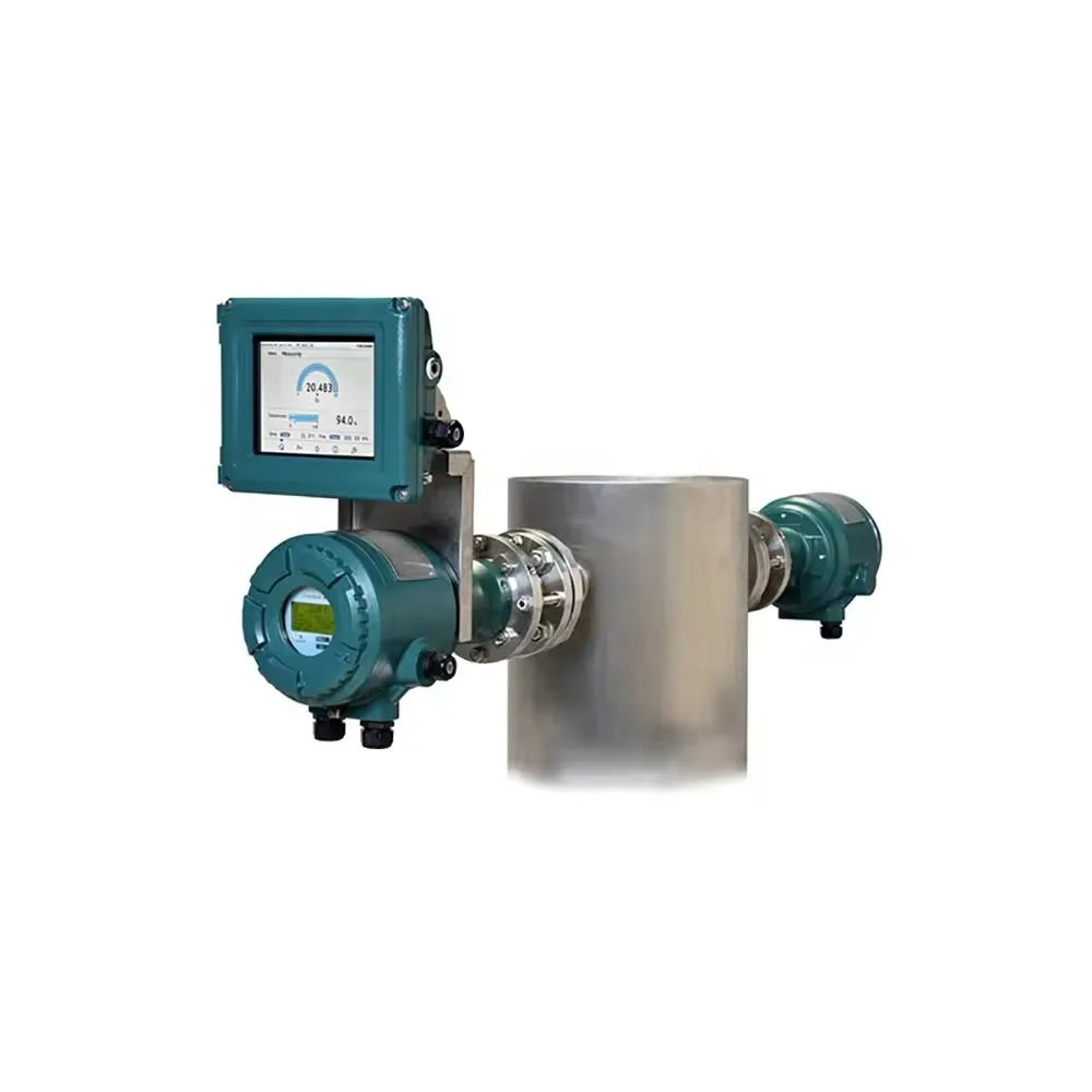
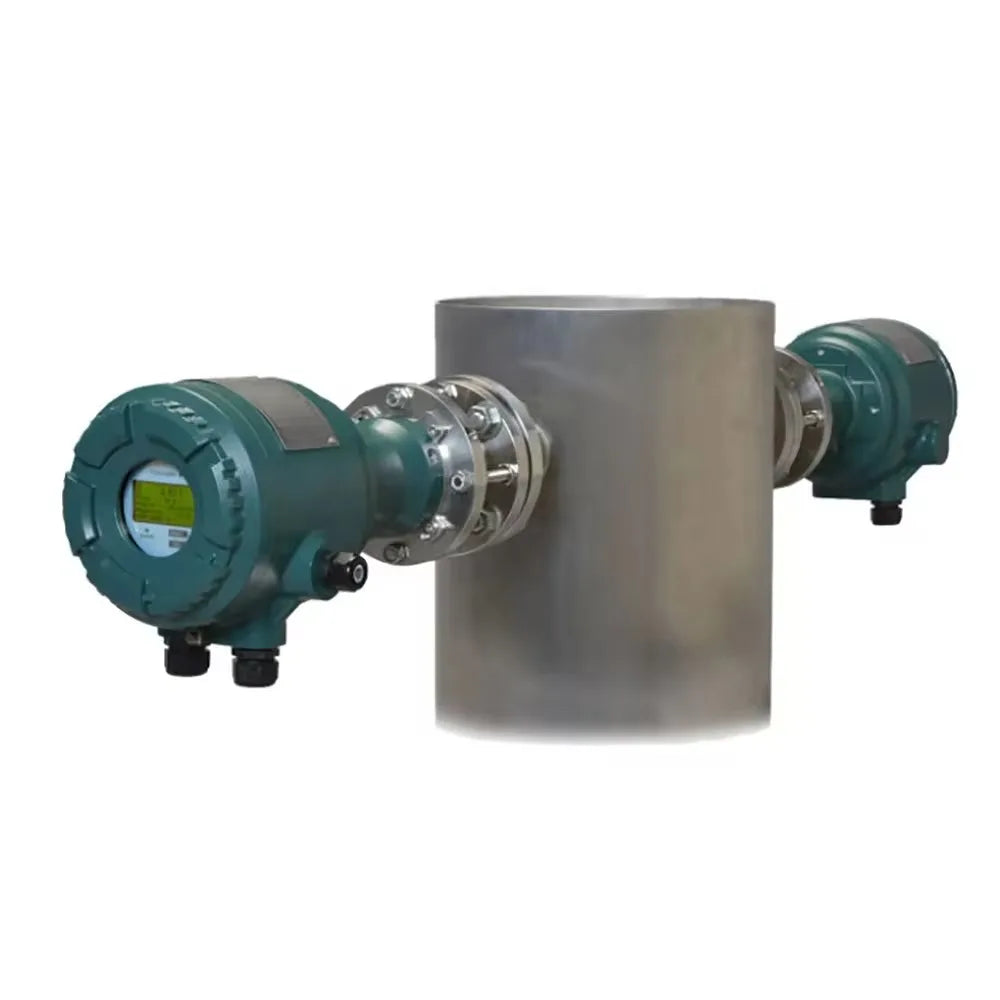
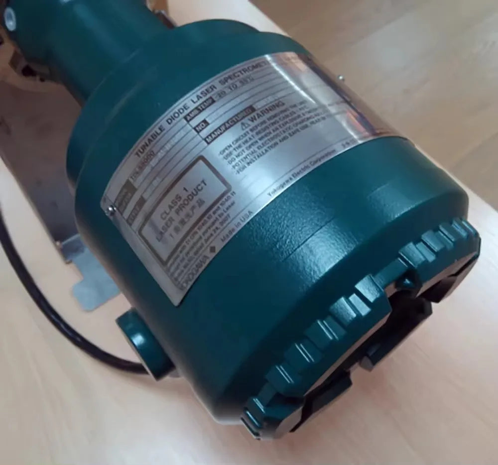
Description
Shipping
Yes, we ship worldwide. We offer FREE shipping or if you want express delivery, you can choose the service and shipping costs will apply, they will be added at checkout.
No, taxes are included and with free shipping.
We use all major carriers, and local courier partners. You’ll be asked to select a delivery method during checkout.
Yes, we do offer free shipping to your country.
Product
We always aim for make sure our customers love our products, but if you do need to return an order, we’re happy to help. Just email us directly and we’ll take you through the process.
Other
You can contact us through our contact page! We will be happy to assist you.
Any question?
If we still haven't answered your question, you can contact us below and we will get back to you as soon as possible.